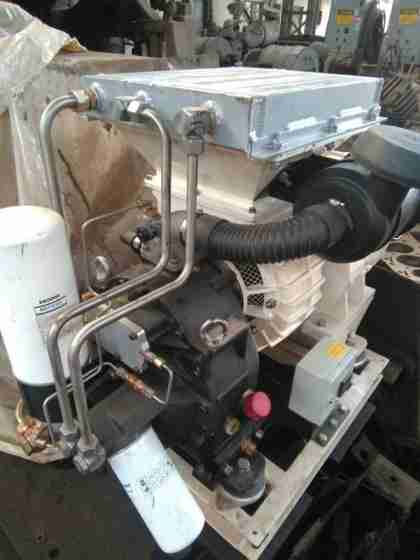
Purpose of the Project: The objective is to replace the damaged reciprocating compressor, which is arcane and her spare had run out of stock with a modern and better operational screw compressor with minimal maintenance cost. This prevents down time on the locomotive and profit generation base on running time.
Duration: Ten days.
The rotary compressor and the reciprocating compressor belong to the class of positive displacement compressors. They both have a pressure difference of the vibrational molecules between the intake and exhaust by displacement of solid boundary.
However, the mode in which they perform this activity differs.
THE RECIPROCATING COMPRESSOR
Reciprocating compressors generally, employ piston-cylinder arrangement where displacement of piston in cylinder causes rise in pressure. They are capable of giving large pressure ratios but the mass handling capacity is limited or small. Finally, they could operate as single acting or double acting compressor; while single acting compressor has one delivery stroke per revolution, double acting works on two delivery strokes per revolution of crank shaft.
The label for fig 1 below:
- Crankshaft
- Drain plug
- Peep hole glass
- Balance block
- Oiling needle
- Crankshaft
- Piston and connecting rod
- Oil plug
- High pressure cylinder
- High pressure cylinder valve
- High pressure cylinder head
- Low pressure relief valve
- Air filter
- Breathing pipes
- Coupling
- Oil level indicator
- Indicator drain cock
- Low pressure cylinder
- Low pressure cylinder valves
- Low pressure cylinder head
- Inter-cooler
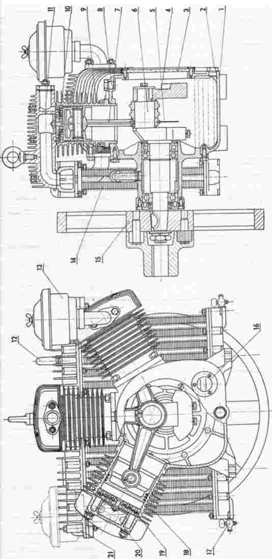
Fig 1 The Reciprocating Compressor
THE ROTARY COMPRESSOR
Rotary compressors employing positive displacement have a rotary part whose boundary causes positive displacement of fluid and thereby compression. They are mainly of two types namely;
- Screw Compressor.
- Vane Compressor.
Both are capable of running at higher speed and can handle larger mass flow rate than reciprocating compressors of positive displacement type.
In the course of the project, attention is on the screw compressor as being the substitute compressor.
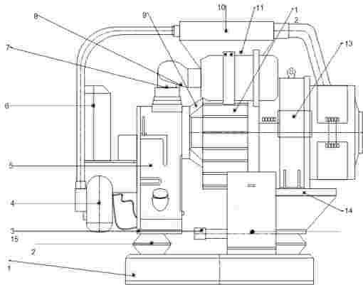
Fig 2
- Foundation base
- Vibrational damper
- Air outlet to Reservoir.
- Oil filter
- Air compression housing.
- Oil-water separator
- Air Intake channel
- Indicator of Air filter
- Connecting flange
- Air Cooler chamber
- Wind scooper
- Fan Blower
- Electric Motor
- Motor base
- Electrical junction box
- Air filter
- Lifting hook
- Oil gauge glass
- Oil relief valve.
- Safety valve.
Parameters between both compressors.
In a project of such ingenuity, the major factors placed under consideration are the parameters between both compressors. A distinctive analysis of the working capacity of both motors and pumps are mainly to ensure the locomotive brake system is at it optimum air pressure for maximum application.
A tabulated comparison of both compressors is illustrated below:
| Technical data | 3W – 1.6/9 (Reciprocating) | BT – 1.6/10AZ (Rotary) |
|---|---|---|
| Compressing device | Three shaped cylinders | Two parallel axis helical shaft |
| Rated capacity (m³/min) | 1.6 | 1.6 |
| Rated discharge pressure (Kpa) | 900 | 1000 |
| Rated motor power (Kw) | 13 | 15 |
| Control voltage (V) | 110 | 110 |
| Rated speed (rpm) | 1500 | 2850 |
From both data, a perfect operation is possible when the air screwed compressor substitutes the reciprocating compressor on a single locomotive.
Comparison between the reciprocating and the screw compressor.
| PARAMETERS | RECIPROCATING | ROTARY SCREW |
|---|---|---|
| Efficiency at full load | High | High |
| Noise level | Noisy | Quiet. if enclosed |
| Size | Large | Compact |
| Oil carry over | Moderate | Low |
| Vibration | High | Less |
| Wear rate | Many wearing part | Very few wearing |
| Capacity | Low-high | Low-high |
| Pressure | Medium-very high | Medium high |
From their characteristics, the screw compressor possesses a better quality with the capability to replace the reciprocating of equal rating.
Graphical representation on the work done on a screw compressor.
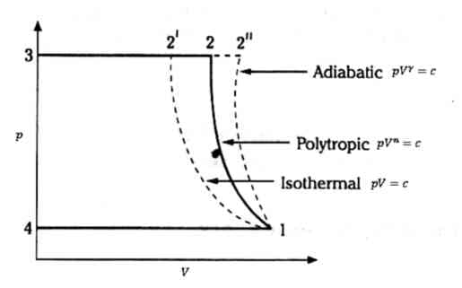
Fig 3
From the above diagram, Constant pressure line 4-1 represents the suction stroke. The air is then compressed adiabatically (process line 12”,) and is then forced out of one of the helices at constant pressure (process 2”3). Area 12”34 represents the work. If the compression is carried out isothermally, then it follows the curve 12‟ which has fewer slopes than both isentropic and polytrophic processes. This work done that is area 12‟34 in isothermal process is considerably less than that due to adiabatic compression. Thus, compressor will have higher efficiency if compression follows isothermal process. It is not possible in practice as to achieve isothermal process, as the compressor must run very slowly. In practice compressors run at high speeds which results in polytrophic process.
The workforce
A team of dedicated, highly skilled and technical in their individual field had the approval of the project coordinator with their specialization in this form:
Mechanical - two
Electrical - two
Welder - one
The workforce comprises of a six-man project team, which includes the project Supervisor.
Materials in use.
Before installation, the screw compressor went through a complete overhaul in which most key components were replaced. The major ones are as follows:
| S/N | MATERIALS |
|---|---|
| 1 | Foundation bed |
| 2 | Oil-water separator filter |
| 3 | Conical bearings |
| 4 | Roller bearings |
| 5 | Air intake filter |
| 6 | Oil filter |
| 7 | Screw shaft rubber seal |
| 8 | A gallon of lubricant oil |
| 9 | Multiple rubber seals |
| 10 | Emery cloth |
| 11 | A gallon of thinner |
The design of the foundation
A huge factor is placed into consideration when the thought of installing the screw compressor is considered. Such as: the compressor weight, assessment to atmospheric air, vibrational level, total alignment between the pump and motor with the locomotive base etc.
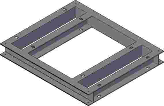
Fig 4. The foundation base
The welded 5mm thick mild steel bar foundation has four shocking absorbing vibrational dampers that support the compressor as she is firmly bolted to the dampers.
Installation steps of the screw compressor.
- Design and construct by welding the foundation bed on the locomotive floor.
- Weld the foundation bed on the locomotive floor.
- Mount the compressor on the vibration dampers and ensure it is properly sited.
- Fasten by bolting the mounted compressor on the vibration dampers making use of the appropriate bolt.
- With the appropriate tool, check for inclination and alignment from the surface. Be certain that the maximum inclination to the base is not beyond 14 degrees to avoid unbalance and unusual vibration while operational.
- Check for other alignments and key components e.g. safety valve before piping connections to the main reservoir.
Safety procedures
The best practices were adhering to ensure none of the team completes a successful Task with some scares to take care of.
- All welding was done with the protective eye shield, hand glove and the presence of carbon (IV) oxide extinguisher.
- It was ensured that no current flow across cables during connection.
- Despite working on DC supply, the electrical team was constantly wearing their rubber insulated glove.
- The use of multi meters and other current detecting devices were properly in use.
- For heavy loads, the lifting crane was fully operational.
- A well ventilated and luminous environment was in kept in place.
Challenges during the project.
The joy of an accomplished assignment is the number of obstacles scaled through.
- The greatest hurdle was to seek approval after series of presentation and conviction.
- The design of the foundation bed to ensure minimal alteration and reconstruction was also a considered factor.
- Initially, the non-availability of schematics’ diagrams delayed electrical troubleshooting, which commence with it.
- The welding of air pipes was cautiously for certainty of being air proof at the maximum flow rate.